Here you can find documentation for just about anything you’d need. If you can’t find what you’re looking for, please contact me. Click on the topic below to see a detailed answer for each.
- CDI Set-up Those instructions I made up for MULTI CYLINDER CDI’s and will help you out, give you a better understanding on how to set-up your NEW multi cylinder CDI, how to set up the timing.
- CH Timing Procedure This instructions will help you out on setting out Single and even fire twin cylinder CDI. It also includes a degree wheel
- Saito 120 150 180 Install Instructions
Shows the steps need it to convert a Saito 120/150/180 to glow CDI or full Gasoline Conversion. - Saito R450 Install Instructions
Shows the steps need it to convert a Saito FA450 R3 to glow CDI or full Gasoline Conversion. - CH Universal Timing Device
This kit allows, helps customer to set proper timing for all the engines that owns. - CH Jump Start Ign Instructions
Those are the old instructions for the Jump start used on many engines. Most was used on Zenaoh G45, G62, GT 80.
- Rcexl Smoke Pump
User manual for the New RCexl Gasoline/ Smoke Pump - Servo Simulator
RCexl Servo Simulator User Manual - Single&Dual Sensor Tester
Single and Dual Sensor Output sensor Tester User Manual. - UMS Gas Radial Engine Manual 5 CYL
- UMS Gas Radial Engine Manual 7-50
- UMS Gas Radial Engine Manual 7-90
- UMS Gas Radial Engine Manual 7-160
- UMS Gas Radial Engine Manual 7-260
- UMS Gas Radial Engine Manual 9-115
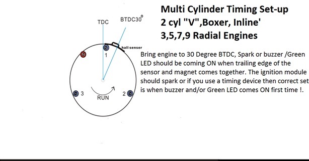
Time 30 Degrees BTDC when sensor/Magnet on cyl #1 first come in contact. Cylinder #1 is ALWAYS the first GREEN after the RED LED.
Now that you have purchased the ignition module, you will need a good battery pack 800 MA or larger. MAKE SURE YOU HAVE THE POLARITY CORRECT.
Red wire is always positive and we always put the positive wire in the center of the Dean’s plug. If in doubt, check with a voltmeter; We have found new packs wired wrong. THE CENTER PIN on your radio plug is not always positive. Airtronics has the positive pin on the outside of the plug. THERE IS NO REVERSE PROTECTION on any of our systems now. While reversed polarity shouldn’t hurt the module, it could damage the sensor. Do not try and run the ignition off the same pack as the radio.
We send most of the modules out without switch harnesses or plugs. Any radio switch harness will work, just make sure you have battery polarity correct before turning on the switch. When in doubt, check it with a volt meter. Some radios have “plus” in the middle and some don’t. Keep all the wires as short as possible and as far from any part of the radio as you can.
We like to use a larger than 800 MA pack on the HD single or twin system. If weight is not a problem use a 1200 mA or larger pack. If you use one of the larger packs, make sure you use a charger rated for the battery pack. You must be able to charge the pack at least 10% of its capacity. A 1200 mA battery needs a 120 mA charger. You cannot leave your 500 mA battery charger on for a longer time and get the pack fully charged.
The early RCEXL ignitions have a sticker that says 4.8 to 6 volts. Six volts was too much for some of these systems. The newer versions of these ignitions have a sticker that says version 2. These are OK with 6 volts. I read on R.C.U. that some of the fliers were using two of the A-123 cells on the RCXL ignition; these cells hold 7.2 volts for quite a long time. I have tested these ignitions with this voltage and the case gets fairly warm so transistor has got to be running pretty hot. You are on your own if you use over 6 volts, any damage caused by over voltage is not covered by warranty. I have been flying the CHXL single ignitions on one Li Poly. This seems to work fine, the engine will start cutting out before the voltage gets low enough to hurt the single Li -Poly. Just do not forget to turn the ignition off or it will ruin your single cell. I am working on a warning for this. With 7.2 volts the battery drain is over 700 MA.
I just have done some battery drain tests.
All tests were done at 8000 RPM.A new single cylinder, Version 2 CHXL Ignition.
- 7.2 Volts -725 mA
- 7 Volts -675 mA
- 6 Volts -650 mA
1. Wrap the ignition module in foam, just as you do a receiver. We usually put the module in a plastic baggie before wrapping in foam. Protect from vibration. I have been asked if it is OK to mount the ignition module on the front of the firewall … beside or below the engine. This is fine but you do need to protect the module from fuel and vibration. I put a couple of cup hooks in the firewall and then place a 1/2″ thick piece of foam under the module. The unit is held to the firewall by rubber bands … simple but effective. Our big engines shake a lot. You MUST protect the module. Please don’t use Super Glue or RTV to glue the module solid to the airframe.
2. Use a good 4.8 volt battery pack; don’t use an old klunker from an old flight-pack. The majority of the problems with the ignition system are caused by bad or undercharged battery packs. Use a charger rated for the battery pack. Test with a load tester (ESV).
3. Keep the ignition module, ignition battery switch and the charging jack as far away from the receiver, receiver-battery-pack, and the receiver battery switch as possible. Keep all wires on the ignition as short as possible.
4. Do not use a metal push rod to the engine throttle or steerable nose wheel. Do not use a metal throttle cable, even if it has nylon ends.
5. Mount the throttle servo at least 8” from the engine.
6. On the H.D. system with the ground pigtail, do not solder a ground terminal lug to the shielded pigtail … crimp this on. Solder will flow up the lead and then it cannot flex, causing possible breakage. If this ground lead comes off, the engine usually will continue to run, which may cause interference to the radio. The best method is to use a hose clamp and clamp the ground braid to the spark plug hex. DO NOT attach the ground wire to a carb mounting bolt. Some of these bolts just go into a fiber block and are not grounded.
If you want to remove the Bosch cover to get the spark plug wire through a hole in the airframe, unsolder the ground from the Bosch cover and unscrew the cover from the wire. If the cap doesn’t unscrew easily you may have to heat it with a monokote gun to soften the sealant. After you have installed the ignition in the airplane, use a new piece of heat shrink on the plug wire, and screw the cover back on. The cover should be screwed on about four turns. If you want to remove the rubber boot, reach up into the boot with a small screwdriver and push the spring terminal back out of the boot. Use some lube on the spring to help get it back into the boot. You MUST protect the spark plug lead from chaffing. A fiberglass cowl can cut the plug wire in just one flight. Use a piece of vacuum hose or a grommet to protect it.
7. Make sure that none of the wires from the module or battery pack are routed where they may pass over a sharp bulkhead, or are pinched where vibration could cause them to rub through the insulation. This could cause a fire in your airplane. It could happen with radio equipment also I nearly lost my Laser with a short in the battery pack wires, so beware.
8. Range check your radio with the engine off and then running. There should be less than a 15% decrease in range with the engine running.
OTHER SUGGESTIONS
1. If you are in a high humidity area, use some Silicone dielectric grease on the spark plug and cap to prevent “arc over” onto the spark plug.
2. If you are running your engine inverted, run the engine as dry as you can on fuel when shutting down for the day. Store the airplane with the engine upright if possible. If you can’t store with the engine upright, remove the spark plug for storage.
3. Do not install a micro switch on top of a servo as a radio operated kill switch and run wires ahead to the ignition. If you want to use a micro switch for a kill switch (a good idea) or smoke pump, use an Ace switch box and a nylon rod to operate it.
If all else fails, read the instructions and troubleshooting guide one more time. If you still have a problem, give us a call. We are not always in the shop or office. Keep trying.
HINTS AND TROUBLE SHOOTING FOR ALL ENGINES WITH CH IGNITION SYSTEMS
1. The number 1 problem is still with the battery. Check battery pack voltage with a good load tester. Check the battery pack voltage with an ESV. Then check voltage at the center pin of the female 3-pin Deans plug coming out of the module. It’s red, white and black. Unplug the pulse switch from the module sensor switch, then switch “on.” of course! This should be the same as battery pack voltage. If the voltage is OK here, the battery pack and switch are OK. If no voltage appears, make sure the battery and switch are wired correctly.
2. With the ignition switch on, ground the white wire on the female 3 pin Dean’s plug (same plug as step 1). When you break this ground, the ignition should fire the plug. If it does, then the problem is the pulse switch or the magnet reversed … check the pulse switch or replace it with a known good one.
3. The black end of the magnet must go toward the pulse switch. If up to this point everything checks OK, “flag” the pulse with the other end of the magnet or use another magnet. Just pass the magnet back and forth past the pulse switch. We could have marked the magnet wrong. If this check makes the system fire, then the magnet must be turned around.
4. It is normal to hear a spark fire inside the module case if you trigger the ignition with the spark plug wire removed and not grounded. Do not do this unnecessarily. If you get a double spark as the magnet approaches and once when it leaves the pulse switch, then the battery is bad or needs recharging.
5. If after making the above tests you do not have a spark … send the module to us for repair or replacement. I would like to have the battery pack switch harness and pulse switch also, if possible. If the system came from an engine manufacturer, send it directly to C & H for repair. If the system is under 90 days old it will be repaired or replaced under warranty.
6. Make sure the chain saw type engines are using a resistor type spark plug.
7. The new McDaniel spark plug ¼ x 32 cap is working very well and has just about stopped all complaints of R.F.I.
The McDaniel plug caps go on the spark plug very hard at first.
VERY IMPORTANT – With this cover you must push it over the hex on the spark plug and then turn it to lock it on the spark plug.
When all else fails … read the instructions. If after doing this you still cannot get a spark or get your engine to run right … do not fight it for days on end … or take it to your “local engine expert.” Give me a call. If we cannot figure it out over the phone, I will be happy to look at the complete set up and test run it.
Is 2.4 GHz immune to Ignition spark noise (RFI)? At first we heard reports, that nothing would bother the 2.4. Now is seems the consensus is to take the same precaution you would with 72 GHz. I’m for this. I think enough RF noise could get into a servo amp and mess up the whole works. There have been reports of problems that fliers think are caused by ignition noise. The complaint starts like this, when I start my engine the radio goes nuts .When I stop the engine the problem goes away, so it has got to be ignition problems. I have to believe these are vibration induced problems. When they stop the engine the vibration goes away this problem can also be caused by the metal spark plug cap not pushed all the way down on the spark plug, the wire snap ring must be all the way past the hex on the spark plug when installed correctly. The wrong cap and spark plug combination also causes a lot of problems.
I have done some testing on the 2.4 Futaba FASST systems. I built a ignition with no shielding, no resistor wire No metal cap on the spark plug, no case or cover on the ignition system and installed about four inches from receiver battery pack and receiver. Using a resistor spark plug .Engine running I had solid control at 180 steps about over 500 feet. That was with the range check button pushed in on the transmitter module. I moved the transmitter around in all positions and no funnies. I installed a non-resistor spark plug and a different story. Only had about 50 feet with range check button pushed. So…too much noise will bother a 2.4 system. I would guess the noise could be getting into the servo amps. The noise was so bad it would peg my RFI meter up to about 75 feet. I know it would drive a FM completely nut’s. We have done the same test on a Spectrum with the same results. So to make a long story short RFI noise will bother a 2.4 if bad enough. No one would ever fly an ignition like this, I hope, and always use a resistor spark plug if you can. The 10MM, NGK CM-6 is a none resistor spark plug so it should have a full shielded plug cap and a resistor wire or resistor in the plug cap. CH uses a resistor wire and a full metal spark plug cap. We will check the other 2.4 systems when we have a chance and report on these. So to backup where we started, use the same precautions you would use with a 72 system. Why ask for a problem. Seen some flyers are using the same battery pack for both radio and Ignition. I do not know anything about this but may check it out; this will not be on front burner for things to get done.
First, examine the spark plug lead to see if OK to install a new boot and cap. If the plug wire is covered with heat shrink and it is worn through to the metal braid, this will not hurt just clean it off and put some tape on it. If the braid is worn through but not worn into the plug, lead core, wrap it with some kind of braid and tape tightly. Solder wick works good to wrap over the damaged spot on the braid it can be spot soldered on if you wish.
We can replace the braid and heat shrink but not the spark plug wire on the CHEXL & RCEXL Ignition. If the center core of the lead is cut or almost worn to the center conductor, you will need a new spark plug lead. The spark plug lead itself cannot be replaced and you are in the market for a new ignition. You can put a couple of pieces of heat shrink tubing over the bad spot then put on new braid and heat shrink on complete plug wire.
Check your spark plug wire over good before you order a new cap then you can order new braid and heat shrink. If your spark plug lead is not covered with heat shrink this would be a good time to do so. The spark plug lead is not replaceable on many ignition systems.We can replace any part on the CH Ignition system.
 1. Remove your old spark plug cap and boot and the entire old heat shrink, do not remove the heat shrink that covers the braid and wire. Cut the end of the wire off clean. You will probably shorten the plug lead about ½-to¾ inch when you install the new boot and cap. Remove about 1&1/4 inch of the heat shrink and leave the braid and inner plug lead exposed.
2. Slide a 1 ½ inch of ½ heat shrink over the plug wire then a 1 ¼ inch of 3/8 heat shrink and ¾ inch 3/8 heat shrink and last the wire crimp ring.
3. Install the spark plug terminal spring by hooking the longer end into the position that you want to be the top of the plug wire, cut the inner plug wire off so that the spring will just go past the end of the plug wire with some resistance. This will help to hold the plug wire in place, then hook in the short lead and squeeze together with pliers. Install a ½ inch length of 3/8 heat shrink over the end of the spark plug wire and shrink with a heat gun or lighter. I put a small amount of medium CA on the spring wires before shrinking the short piece of heat shrink.
4. To install the silicone plug boot lube the boot with some liquid soap or silicone lube and push the spring into the boot. The longer wire on the spring terminal goes to the top of the plug boot. Make sure the terminal is straight in the boot. Push your spark plug into the boot and make sure the top button goes into the spring. If the spring is not straight, take a small screwdriver and square it up. Be careful and do not puncture or tear the boot.
5. now the fun part, Bend the tabs over past 90 degrees on the steel shell. Use a flat-nosed pair of pliers. Be careful and do not bend the flange on the shell .Lay the boot in the cover that has the tabs then hook the other shell under the front tab and two top tabs. Squeeze the bottom of the shells together and hook the bottom tab slide the braid up over the wire and covers. Now slide the crimp ring up over the braid and cover shells. Trim off excess braid with a sharp pair of cutters. Do not crimp the ring. Install the snap ring. I do this with a set of square-nosed pliers. If you have a pair of snap, ring pliers that will work for this go ahead and use them. Usually when I try to use snap ring pliers the ring goes flying off into the wild blue yonder never to be seen again. Install the gap in the snap ring 45 degrees to the seams on the cover. Do not distort the ring, it must be tight to hold the cap on the spark plug and make a good ground. Use some sort of clamp and squeeze the shells together and then crimp the tabs down with a good pair of square-nosed pliers. I have a pair of pliers that I have cut notches in to help bend the tabs down. I usually have about a dozen pair of pliers out by the time I am done. A small pair of vice gripes work, good for a clamp if you pad the jaws good so you do not scratch the beautiful stainless steel cover.
6. Crimp the retaining ring on the back of the cover. Put some vinyl glue around the crimp ring and slide the short piece of heat shrink over the ring and shrink it down, then slide the other two pieces of shrink over the rear of the cap and shrink with a heat gun. Set back and admire your work. Read CHRCEXL instructions to install and remove the cap from the spark plug. We solder the tabs to make the cap a little stronger. Do not try and do this if you do not have the solder flux for stainless steel. You will just make a mess of it.
7. If you are installing the cap for the NGK-CM-6, 10MM spark plug there are a few changes. If your ignition uses a resistor spark plug lead (carbon core). You do not need a resistor in the cap .If your ignition has a copper stranded core you need to install a resistor in the cap. We will install the 5.1K resistor in the cap if we know that is what you need. There are some other small changes as follows when you use the CM-6 spark plug. This is not a resistor plug
8. If you are installing the CM-6 cap on a stranded wire spark plug lead, leave only about one inch of center conductor exposed fold the braid back just like we did above for the larger spark plugs. Using the small brad (nail) found in your plug cap package poke a hole into the center of the spark plug conductor twisted copper core .Go in about 3/8 inch. Center the resistor lead in the spark plug boot and push the resistor lead into the hole in the plug lead center conductor. Use a small amount of thick CA on the plug wire. Hold the boot tightly right where the resistor is in the boot. You do want to push the other end of the resistor lead out through the silicone boot. This will cause the sparks to leak out. The rest of the cap is installed the same as the larger plug.
If your ignition system has a carbon core resistor lead, you do not need a resistor in the cap. On this lead push the small brad into the carbon core about 3/8 inches with a small amount of CA on the nail. Leave the nail in the wire and cut off to about ¼ inch long. Push the spark plug lead into the boot and the nail will go between the coils on the spring contact, and then when you push the spark wire plug into the boot, it will all squeeze together and make a good contact. DO NOT leave the nail long enough to go clear through the boot.
We have come up with a few new things about our CHXL ignitions.
First we are very pleased with our CHXL ignitions. We have sold over 2000 of them, with two coming back with problems. One was a 10 MM-System for the NGK CM-6 spark plug. It had a leak in the silicone spark plug boot to ground. We repaired this and returned it to our customer. The other was user caused. One of the male pins on the Futaba plug had pushed to one side and missed the female pins. If these plugs try to bind up and will not push together easily, look at the male pins and align and center them with an exacto knife blade. There are fliers who still have problem getting the steel cap off the spark plug. READ OUR INSTRUCTIONS. Insert a small 1/8 wide flat screw driver between the steel shells and turn it sideways and pry the cap open. The cap will then come off easily. You may need three hands to do this. You can make the cap a little easier to get off by rounding the points on the hex of the spark plug with a Dremel sanding drum.
DO NOT use pliers on the steel cap this will void the warranty. Besides it makes it look bad. We have ignitions sent back with the steel cap ruined and spark plug wires ruined by rubbing on something.We have been preaching this for over 20 years. Protect the spark plug wire any place it can rub on anything. Use some soft vinyl hose or vacuum hose. Slit the hose and put it around the spark plug wire and tie with nylon ties. AT least 50% of the units we get back for repair have ruined spark plug wires. Remember the spark plug wire is not replaceable on the CHXL or RCEXL Ignitions and many others. This kind of damage is not covered by warranty. This is improper installation.
Make sure you are using the correct spark plug with your CHXL steel cap. We have three sizes of Steel Spark plugs caps with silicone boot.
First, examine the spark plug lead to see if OK to install a new boot and cap. If the plug wire is covered with heat shrink and it is worn through to the metal braid, this will not hurt just clean it off and put some tape on it. If the braid is worn through but not worn into the plug, lead core, wrap it with some kind of braid and tape tightly. Solder wick works good to wrap over the damaged spot on the braid it can be spot soldered on if you wish.
We can replace the braid and heat shrink but not the spark plug wire on the CHEXL & RCEXL Ignition. If the center core of the lead is cut or almost worn to the center conductor, you will need a new spark plug lead. The spark plug lead itself cannot be replaced and you are in the market for a new ignition. You can put a couple of pieces of heat shrink tubing over the bad spot then put on new braid and heat shrink on complete plug wire.
Check your spark plug wire over good before you order a new cap then you can order new braid and heat shrink. If your spark plug lead is not covered with heat shrink this would be a good time to do so. The spark plug lead is not replaceable on many ignition systems.We can replace any part on the CH Ignition system.
1. Remove your old spark plug cap and boot and the entire old heat shrink, do not remove the heat shrink that covers the braid and wire. Cut the end of the wire off clean. You will probably shorten the plug lead about ½-to¾ inch when you install the new boot and cap. Remove about 1&1/4 inch of the heat shrink and leave the braid and inner plug lead exposed.
2. Slide a 1 ½ inch of ½ heat shrink over the plug wire then a 1 ¼ inch of 3/8 heat shrink and ¾ inch 3/8 heat shrink and last the wire crimp ring.
3. Install the spark plug terminal spring by hooking the longer end into the position that you want to be the top of the plug wire, cut the inner plug wire off so that the spring will just go past the end of the plug wire with some resistance. This will help to hold the plug wire in place, then hook in the short lead and squeeze together with pliers. Install a ½ inch length of 3/8 heat shrink over the end of the spark plug wire and shrink with a heat gun or lighter. I put a small amount of medium CA on the spring wires before shrinking the short piece of heat shrink.
4. To install the silicone plug boot lube the boot with some liquid soap or silicone lube and push the spring into the boot. The longer wire on the spring terminal goes to the top of the plug boot. Make sure the terminal is straight in the boot. Push your spark plug into the boot and make sure the top button goes into the spring. If the spring is not straight, take a small screwdriver and square it up. Be careful and do not puncture or tear the boot.
5. now the fun part, Bend the tabs over past 90 degrees on the steel shell. Use a flat-nosed pair of pliers. Be careful and do not bend the flange on the shell .Lay the boot in the cover that has the tabs then hook the other shell under the front tab and two top tabs. Squeeze the bottom of the shells together and hook the bottom tab slide the braid up over the wire and covers. Now slide the crimp ring up over the braid and cover shells. Trim off excess braid with a sharp pair of cutters. Do not crimp the ring. Install the snap ring. I do this with a set of square-nosed pliers. If you have a pair of snap, ring pliers that will work for this go ahead and use them. Usually when I try to use snap ring pliers the ring goes flying off into the wild blue yonder never to be seen again. Install the gap in the snap ring 45 degrees to the seams on the cover. Do not distort the ring, it must be tight to hold the cap on the spark plug and make a good ground. Use some sort of clamp and squeeze the shells together and then crimp the tabs down with a good pair of square-nosed pliers. I have a pair of pliers that I have cut notches in to help bend the tabs down. I usually have about a dozen pair of pliers out by the time I am done. A small pair of vice gripes work, good for a clamp if you pad the jaws good so you do not scratch the beautiful stainless steel cover.
6. Crimp the retaining ring on the back of the cover. Put some vinyl glue around the crimp ring and slide the short piece of heat shrink over the ring and shrink it down, then slide the other two pieces of shrink over the rear of the cap and shrink with a heat gun. Set back and admire your work. Read CHRCEXL instructions to install and remove the cap from the spark plug. We solder the tabs to make the cap a little stronger. Do not try and do this if you do not have the solder flux for stainless steel. You will just make a mess of it.
7. If you are installing the cap for the NGK-CM-6, 10MM spark plug there are a few changes. If your ignition uses a resistor spark plug lead (carbon core). You do not need a resistor in the cap .If your ignition has a copper stranded core you need to install a resistor in the cap. We will install the 5.1K resistor in the cap if we know that is what you need. There are some other small changes as follows when you use the CM-6 spark plug. This is not a resistor plug
8. If you are installing the CM-6 cap on a stranded wire spark plug lead, leave only about one inch of center conductor exposed fold the braid back just like we did above for the larger spark plugs. Using the small brad (nail) found in your plug cap package poke a hole into the center of the spark plug conductor twisted copper core .Go in about 3/8 inch. Center the resistor lead in the spark plug boot and push the resistor lead into the hole in the plug lead center conductor. Use a small amount of thick CA on the plug wire. Hold the boot tightly right where the resistor is in the boot. You do want to push the other end of the resistor lead out through the silicone boot. This will cause the sparks to leak out. The rest of the cap is installed the same as the larger plug.
If your ignition system has a carbon core resistor lead, you do not need a resistor in the cap. On this lead push the small brad into the carbon core about 3/8 inches with a small amount of CA on the nail. Leave the nail in the wire and cut off to about ¼ inch long. Push the spark plug lead into the boot and the nail will go between the coils on the spring contact, and then when you push the spark wire plug into the boot, it will all squeeze together and make a good contact. DO NOT leave the nail long enough to go clear through the boot.
We have come up with a few new things about our CHXL ignitions.
First we are very pleased with our CHXL ignitions. We have sold over 2000 of them, with two coming back with problems. One was a 10 MM-System for the NGK CM-6 spark plug. It had a leak in the silicone spark plug boot to ground. We repaired this and returned it to our customer. The other was user caused. One of the male pins on the Futaba plug had pushed to one side and missed the female pins. If these plugs try to bind up and will not push together easily, look at the male pins and align and center them with an exacto knife blade. There are fliers who still have problem getting the steel cap off the spark plug. READ OUR INSTRUCTIONS. Insert a small 1/8 wide flat screw driver between the steel shells and turn it sideways and pry the cap open. The cap will then come off easily. You may need three hands to do this. You can make the cap a little easier to get off by rounding the points on the hex of the spark plug with a Dremel sanding drum.
DO NOT use pliers on the steel cap this will void the warranty. Besides it makes it look bad. We have ignitions sent back with the steel cap ruined and spark plug wires ruined by rubbing on something.We have been preaching this for over 20 years. Protect the spark plug wire any place it can rub on anything. Use some soft vinyl hose or vacuum hose. Slit the hose and put it around the spark plug wire and tie with nylon ties. AT least 50% of the units we get back for repair have ruined spark plug wires. Remember the spark plug wire is not replaceable on the CHXL or RCEXL Ignitions and many others. This kind of damage is not covered by warranty. This is improper installation.
Make sure you are using the correct spark plug with your CHXL steel cap. We have three sizes of Steel Spark plugs caps with silicone boot.
The CH ignition is a CDI system. (CDI = Capacitive Discharge Ignition.) This company is the standard ignition system that is used by more engine mfg than probably all other brands combined. It is reliable, not prone to excessive radio interference and user friendly. There are several methods to charge a capacitor, but this one uses a step up transformer. Using a CDI, you don’t need a flywheel or points. The flywheel is replaced with a simple disc that has a small magnet on it. That magnet is used in conjunction with a hall effect sensor to trigger the ignition to fire.
The standard CH ignition is a simple system that has fixed timing. You set the sensor to trigger at about 27-30 DBTDC, depending on your engine, and that’s where it fires all the time. CH also sells ignition systems with the SyncroSpark timing module built in, or you can add one in-line later. (Read about it below.) Using this ignition system instead of a flywheel and magneto, you can expect to save anywhere from 3-10 ounces. One Husqvarna engine that I converted had an extremely light flywheel ignition, which would offer minimal weight savings if replaced. The Ryobi’s and Homelite’s, on the other hand, have quite large flywheels and you will save about 10oz by replacing them.
For what it’s worth, I highly recommend the CTC version, for any engine. The cost is extra, but its money well spent. Your engine will start much easier, with a lower likelihood of kicking back and biting your fingers. Not only that, you’ll have a much smoother running engine.
What is the Jump Start system that CH Electronics (now CH Ignitions) sells?
 This is from Terry Grant of CH Ignitions, the mfr. of the Jump Start:
It is a battery powered system to boost the magneto output. It will make a hot spark at any RPM, most mags require 600+rpm to fire. It also retards the timing to around 5 deg BTDC so that the engine won’t kick back. Once the engine starts it becomes a stock engine on the mag with no timing control.
At $75.00 for the Jump Start, you’d be better off buying a full ignition system with SyncroSpark. The Jump Start will make the plane easier to start, but it won’t make the engine run better. A full CDI with timing control, on the other hand, will give you the benefits of the retarded starting timing, and also the benefits of retarded timing in the lower power band in addition to saving a little weight.
What is the Syncro Spark that CH Electronics (now CH Ignitions) sells?
 The SyncroSpark is an electronic timing module, which is available as an add-on, or built into the CH Ignition system. Without it, you set the ignition to fire somewhere between 27 and 30 degrees before top dead center. (DBTDC) Your ignition will fire at that point regardless of the rpm the engine is running. When you plug a Syncro Spark in between the sensor and the ignition module, you will have an engine with variable timing on the ignition. It will retard the timing for starting by about 24 degrees, so you can hand start the engine with it firing at about 4 DBTDC. That makes hand starting MUCH easier.
The Syncro Spark also calculates the spark timing (advance/retard) based on the current RPM. When the engine is idling, the spark is retarded significantly, to smooth out the engine. As you increase the throttle, the module senses this and decreases the amount of retard. (Which is like advancing the timing?) This allows the engine to develop more power, since you can time it to run optimally.
For what it’s worth, I highly recommend the SyncroSpark version, for any engine. The cost is $40 extra, but its money well spent. Your engine will start much easier, with a lower likelihood of kicking back and biting your fingers. Not only that, you’ll have a much smoother running engine.
The use of the terms advance and retard are often misused. This is ok, as long as people are communicating, but it’s usually easier to use the appropriate terms to make sure everybody understands. I’ll define the terms just to make it simple.
When an ignition system has the sensor set significantly before TDC, the system will retard the timing to smooth out the idle. Retarding the timing is the act of pausing for a moment before firing the plug. The pause occurs at lower rpm’s, and happens after the sensor detects the timing magnet. This is the method that the CH ignition uses. It was conveniently chosen, I assume, so that the SyncroSpark module could be plugged in line between the sensor and the ignition without any other modifications for the older units without CTC.